
Differential Compound Motor Circuit Diagram
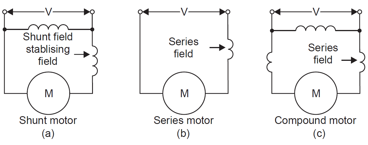
Diagram: DC Shunt motor and characteristics In DC shunt motor, the field winding is connected parallel to the armature. as shown in the above diagram. The DC shunt motor is used where speed regulation is very important. Self-excited Field:

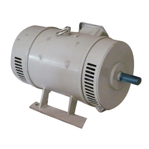
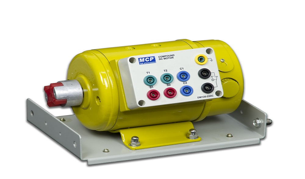
2 H.P DC Compound Motor, 220 Volt at Rs 6000 in Delhi ID 14908221262
Compound Wound DC Motor. Short shunt DC Motor. Long shunt DC Motor. Differential Compound DC Motor. We will now discuss in detail the various different types of DC Motors. If you want to further your study of DC motors, check out our list of basic electrical questions.

Compound Dc Motor Wiring Diagram
(1). Armature current of the motor: (2). Field current of the motor: (3). Supply voltage given to the motor: Where Eb is the back emf and Ra is the armature resistance. Types of Self-Excited Motor The self-excited DC motor is the one in which the current required to excite the field winding is supplied by the motor itself.
Characteristics Of D.C. Compound Motor Electrical engineering
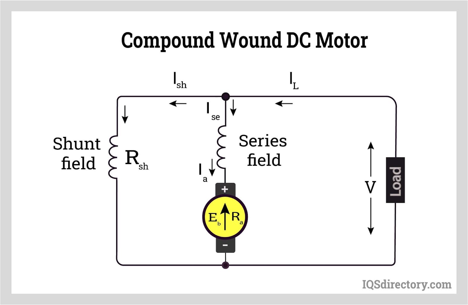
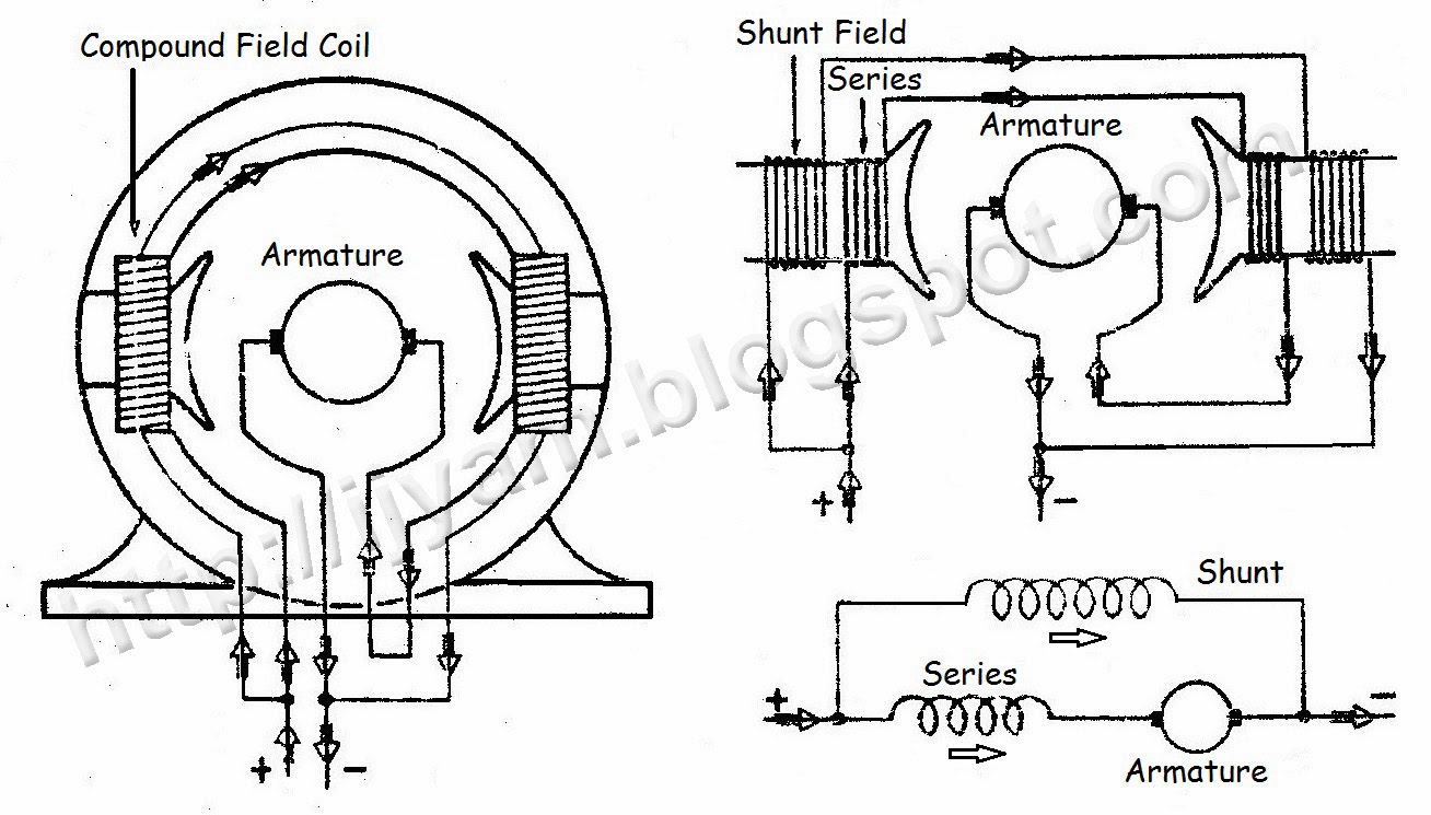
A Circuit Diagram Explaining the Operation of a DC Compound Wound Motor is a detailed illustration that shows how each component in the motor works together. It will typically include a power source, such as a battery, and then a series of switches and relays which control the current flow. Additionally, the diagram will include the motor's.
What Is It? How Does It Work? Types, Uses (2022)
October 26, 2020 by Electrical4U A compound wound DC motor (also known as a DC compound motor) is a type of self-excited motor, and is made up of both series the field coils S 1 S 2 and shunt field coils F 1 F 2 connected to the armature winding as shown in the figure below.
Compound DC Motors Types, Advantages and Disadvantages of Compound
A DC motor is an electrical machine that converts mechanical energy into direct current and vice-versa. Direct current (DC) motors are widely used in today's manufacturing industries. Due to their extensive functionality, DC motors are frequently used in small and medium-sized motoring applications, including robotics and automobiles.
TYPES OF DC MOTORS AND THEIR APPLICATIONS ENGINEERING ARTICLES
Explore the compound DC motor diagram and learn about its construction, working principle, and applications. Understand the different components of a compound DC motor and how they work together to generate rotational motion. Discover the advantages and disadvantages of this type of motor and how it compares to other types of DC motors.
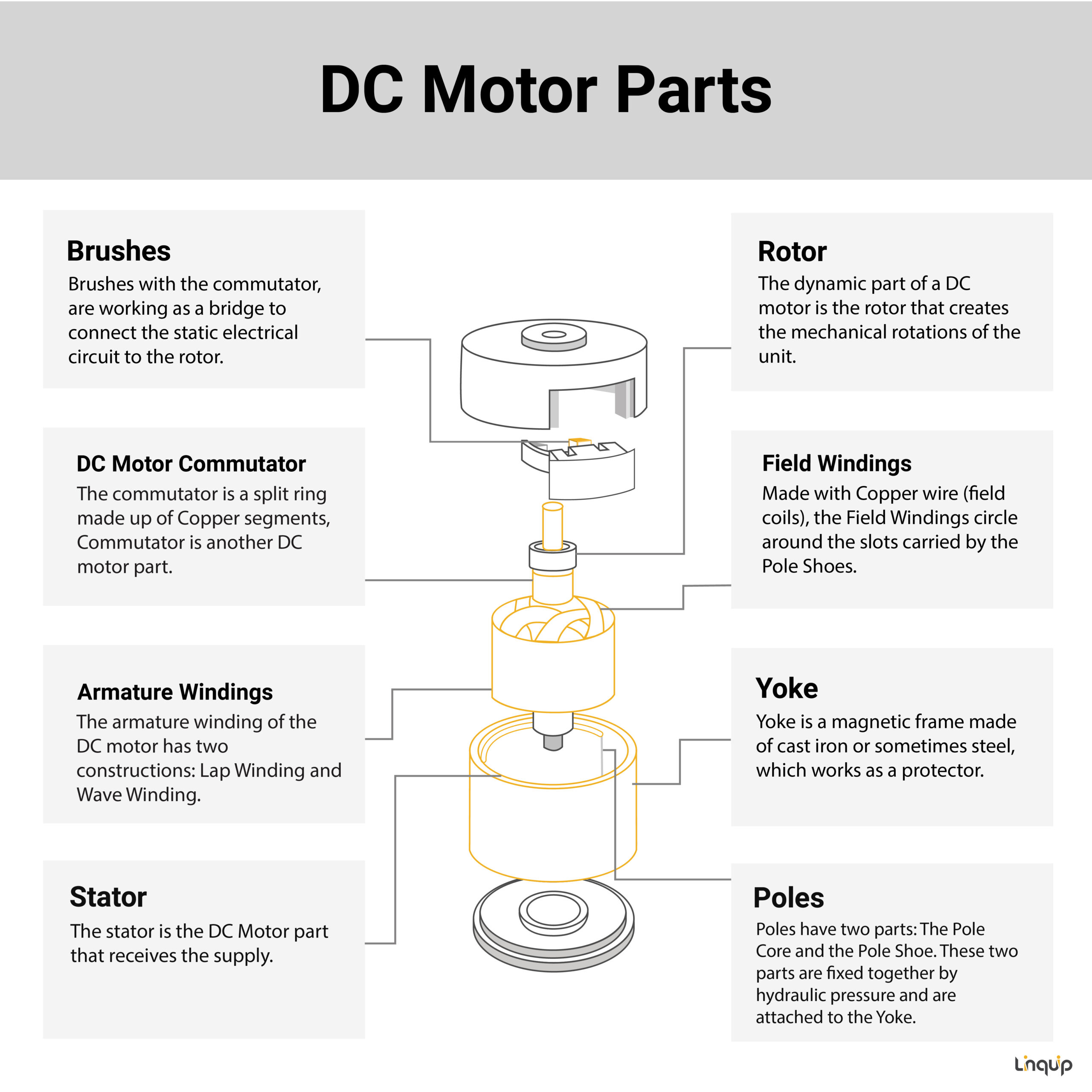
8 Different DC Motor Parts, Structure, Design and Advantages + PDF
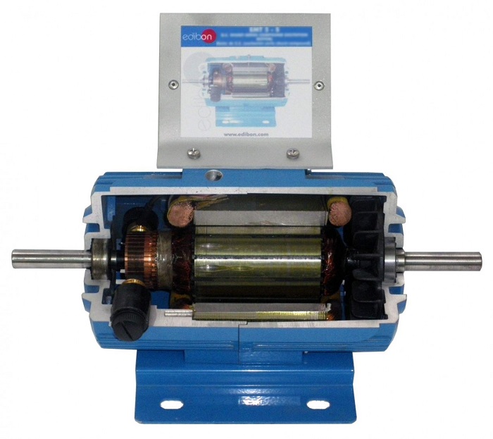
DC Motor Diagram Different Parts of a DC Motor A DC motor is composed of the following main parts:: Armature or Rotor The armature of a DC motor is a cylinder of magnetic laminations that are insulated from one another. The armature is perpendicular to the axis of the cylinder.
Compound Dc Motor Problems And Solutions
August 6, 2022 by Wiring Digital Understanding DC Compound Motor Wiring Diagrams A DC compound motor is a type of DC motor that consists of two independent windings, one wound for series operation and the other wound for parallel operation.

XQD0.753 45V 0.75kW steering motor (hydraulic pump driving motor
PRINCIPLES OF OPERATION The construction of a simple BDC motor is shown in Figure 1. All BDC motors are made of the same basic components: a stator, rotor, brushes and a commutator. The following paragraphs will explain each component in greater detail. FIGURE 1: Stator The stator generates a stationary magnetic field that surrounds the rotor.
conspiração Apresentador livro de bolso motor dc compound arrependerse
DC Series Motor Circuit Diagram In a series motor electric power is supplied between one end of the series field windings and one end of the armature. When voltage is applied, current flows from power supply terminals through the series winding and armature winding.

Compound DC Motor, Dc Electric Motor, Direct Current Motors, डीसी मोटर
A compound DC motor circuit diagram is a graphical representation of the wiring required to power an electric motor. It's used by electrical technicians and engineers to understand the power circuitry and connections between different components in an electric motor.

Dc Shunt Motor Circuit Diagram
The circuit diagram of the short shunt compound dc motor is given below. Characteristics of Cumulative Compound DC Motor Characteristics of Cumulative dc motor are given by curve. This curve is drawn between two different parameters of the compound dc motor. Torque Load Characteristic

Dc Compound Motor Control Panel Wiring / Connection Of Dc Compound
A compound DC motor schematic diagram provides a comprehensive overview of the various electrical and mechanical components that make up a compound DC motor. It shows a complex network of wires, relays and switching devices that control the operation of the motor. It also provides insight into the types of motors available and their specific.

2 H.P DC Compound Motor, 220 Volt at Rs 6000 in Delhi ID 14908221262
The reason behind such a structure amalgamation is to win the better properties of both of these types. A shunt motor brings an extremely efficient regulation for speed, while a series motor has a great and high starting torque. Consequently, a compound DC motor has a great compromise on these features.
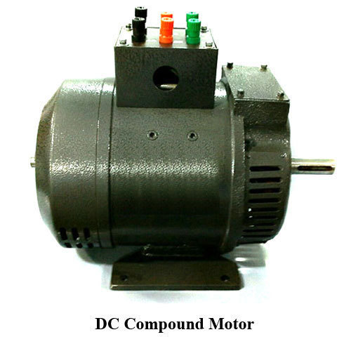
DC Compound Motor, Voltage 12v440v, Power 4kw at Rs 19,500 / Piece
In short, the Compound DC Motor Circuit Diagram is an essential tool for anyone looking to build, maintain, or repair a compound motor circuit. Dc Compound Motor Everything You Need To Know About It Tutorial Dc Motor Working Principle Studiousguy Dc Motor Classification Working Mechanism Applications Advantages