Trailer Brake Wiring Diagram 7 Way Cadician's Blog
Want a brake controller with no installation? Check out Echo™ How to install a trailer brake controller video Brake Control Install: CURT 51120 Discovery Brake Control Watch on Step 1: Disconnect the negative battery cable Any time you work on your vehicle's electrical systems, it is a good idea to disconnect the battery.
wiring diagram for trailer brakes
Use 12 gauge wire if your trailer has two or fewer braking axles and 10 gauge wire if your trailer has three or more braking axles. To wire trailer brakes, you will first need to determine the gauge of wire required. If your trailer has two or fewer braking axles, use a 12 gauge wire.

Wiring Diagram For Trailer With Electric Brakes And Breakaway Wiring
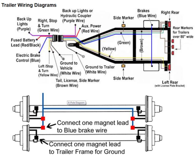
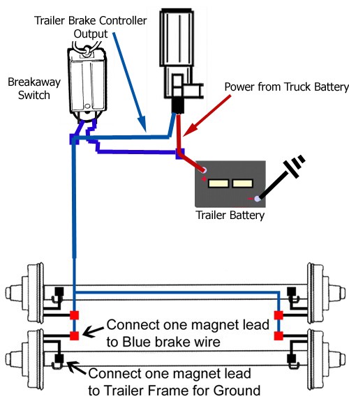
Red wire connects to [cold -non activated] side of brake pedal stop lite switch. Black wire connects to 12VDC positive White wire connects to battery negative Blue - Brake controller output to trailer electric brakes. Improper connection of Positive and Negative wires MAY damage or destroy brake controller. Confirm wiring diagram instructions.

Electric Brakes For Trailer Diagram Wiring Diagram for the Curt 4
If the trailer wiring is running down the left side of the trailer, then we splice the left side brake assemblies into the main electric brake power wire coming from the 7-way connector. We then run a jumper wire from the electric brake power wire to the right side brake assemblies (see photo).

Mya Cabling Camper Trailer Brake Wiring Diagram Pdf Reader
Watch on Two Types of Custom Wiring Custom Wiring Harnesses A custom wiring harness has multiple plugs that are used to 'T' into the vehicle's taillight assembly, drawing power directly from the taillights or from a direct battery connection and providing a standard trailer light wiring connector.
Trailer Wiring Diagrams 7 Way
Click for more info and reviews of this Dexter Trailer Brakes:https://www.etrailer.com/Accessories-and-Parts/Dexter/23-26.htmlCheck out some similar Trailer.

Electric Trailer Brake Wiring Schematic Free Wiring Diagram
Wiring electric trailer brakes may seem intimidating at first, but with the right guidance and a comprehensive wiring diagram, it can be a straightforward process. Whether you're a seasoned DIY enthusiast or a beginner, understanding how to wire electric trailer brakes is essential for towing safety and efficiency.
7 Pin Trailer Wiring Diagram With Brakes Cadician's Blog
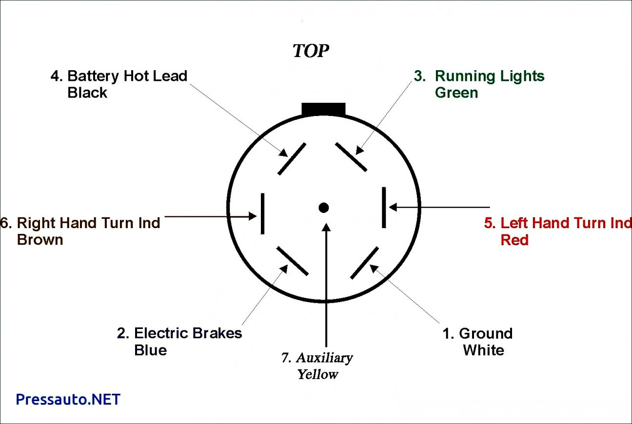
Trailer Wiring Diagram Not sure which wires attach to what on your trailer connectors? Does one of your turn signals not work and you're not sure which wire to inspect? Check out or trailer wiring diagrams for a quick reference on trailer wiring.
Electric Trailer Brake Wiring Diagram / Trailer Wiring Diagram Lights
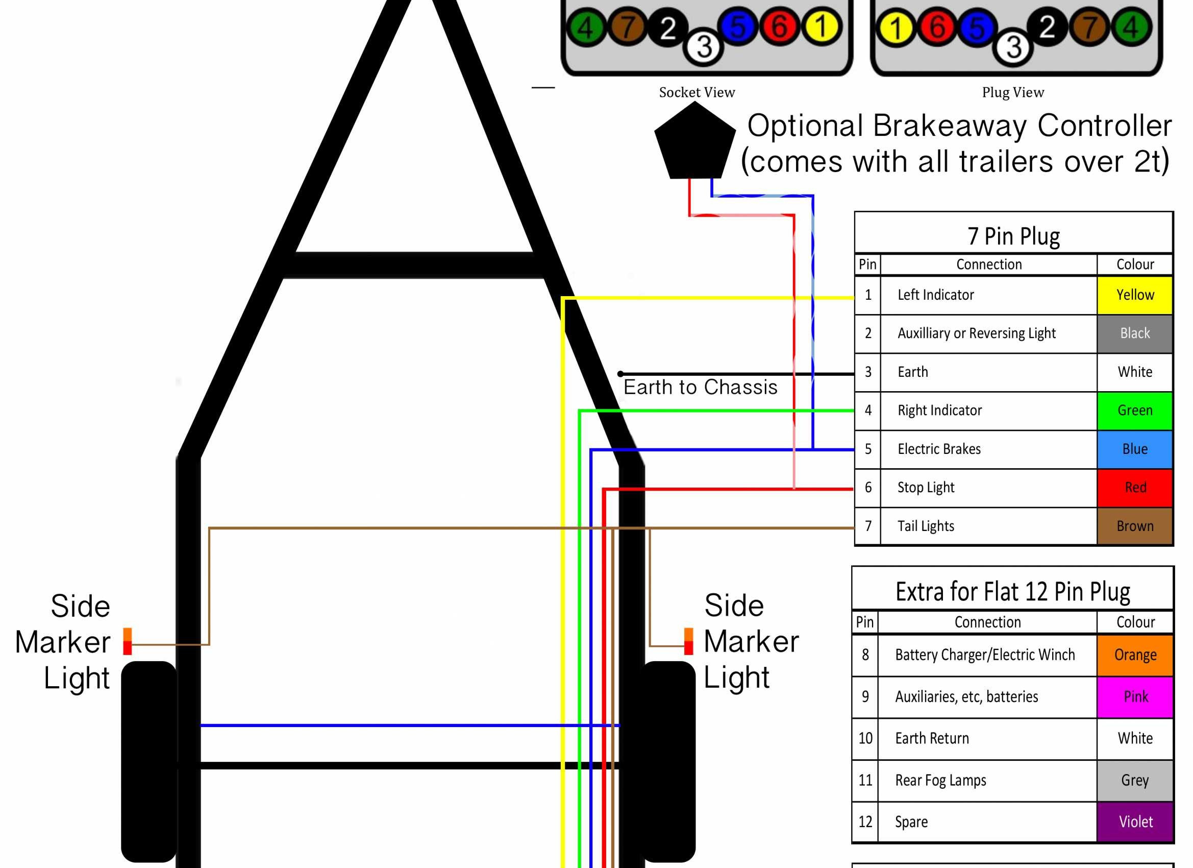
Typically, a utility trailer wiring diagram will include the following components: a power source, a brake controller, a brake switch, brake lights, turn signals, and ground connections. The power source is usually the vehicle's battery, which provides the necessary electrical energy for the trailer's braking system.

Wiring Diagram For Trailer Brakes GALICE WEB
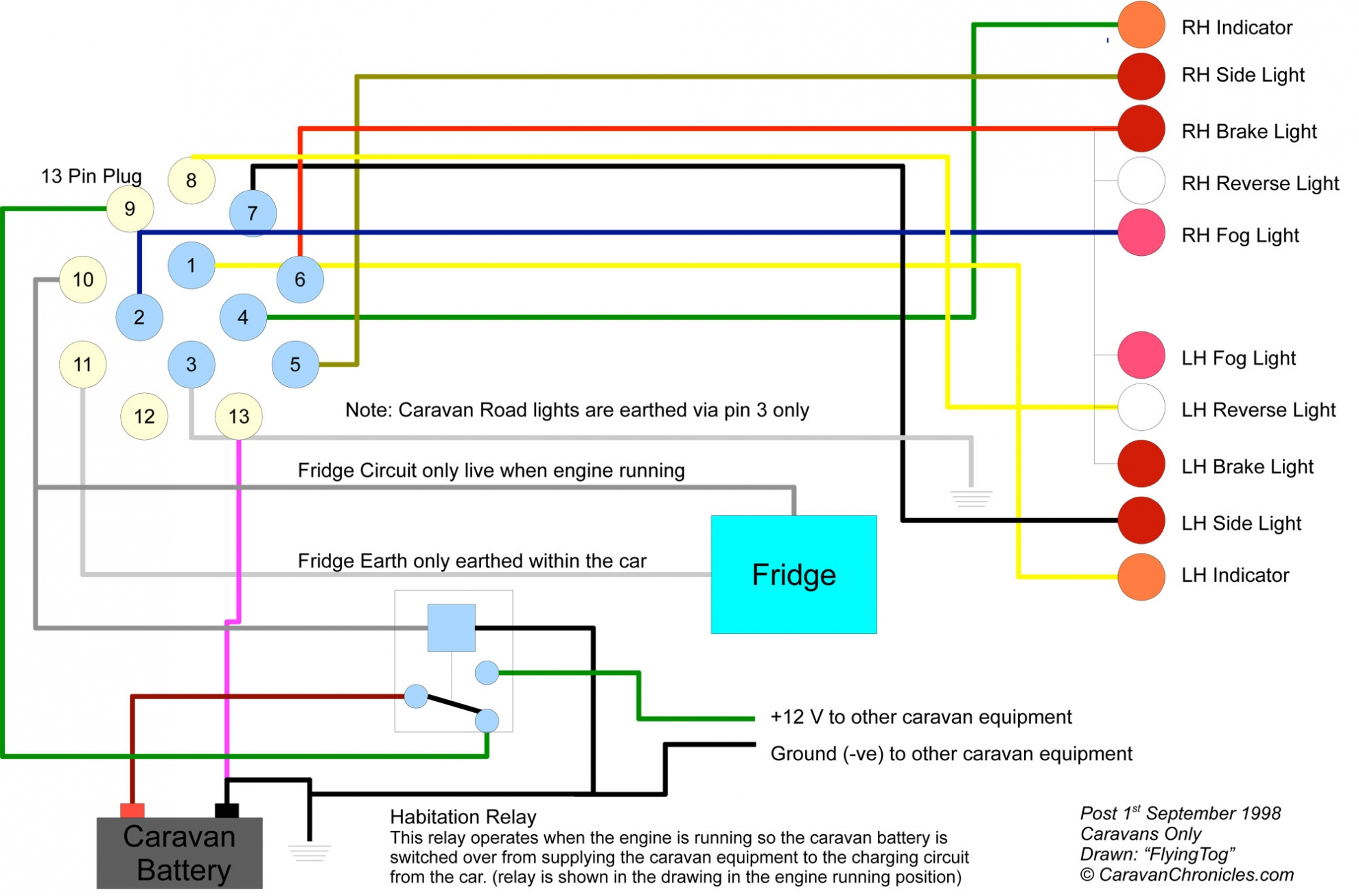
Various connectors are available from four to seven pins that allow for the transfer of power for the lighting as well as auxiliary functions such as an electric trailer brake controller, backup lights, or a 12V power supply for a winch or interior trailer lights.
Wiring Diagram For Trailer Brakes
Feed them into the opposite end of the butter connector. Using a lighter to shrink the butt connector. Take a lighter and hold it up to the butt connector to shrink it. Once it's shrunk, tug on it. Make sure it's nice and strong. Wrapping the butt connector in black electrical tape.
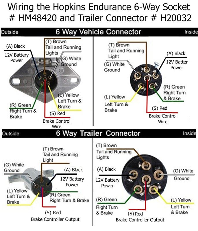
Trailer Brake Plug Wiring Diagram
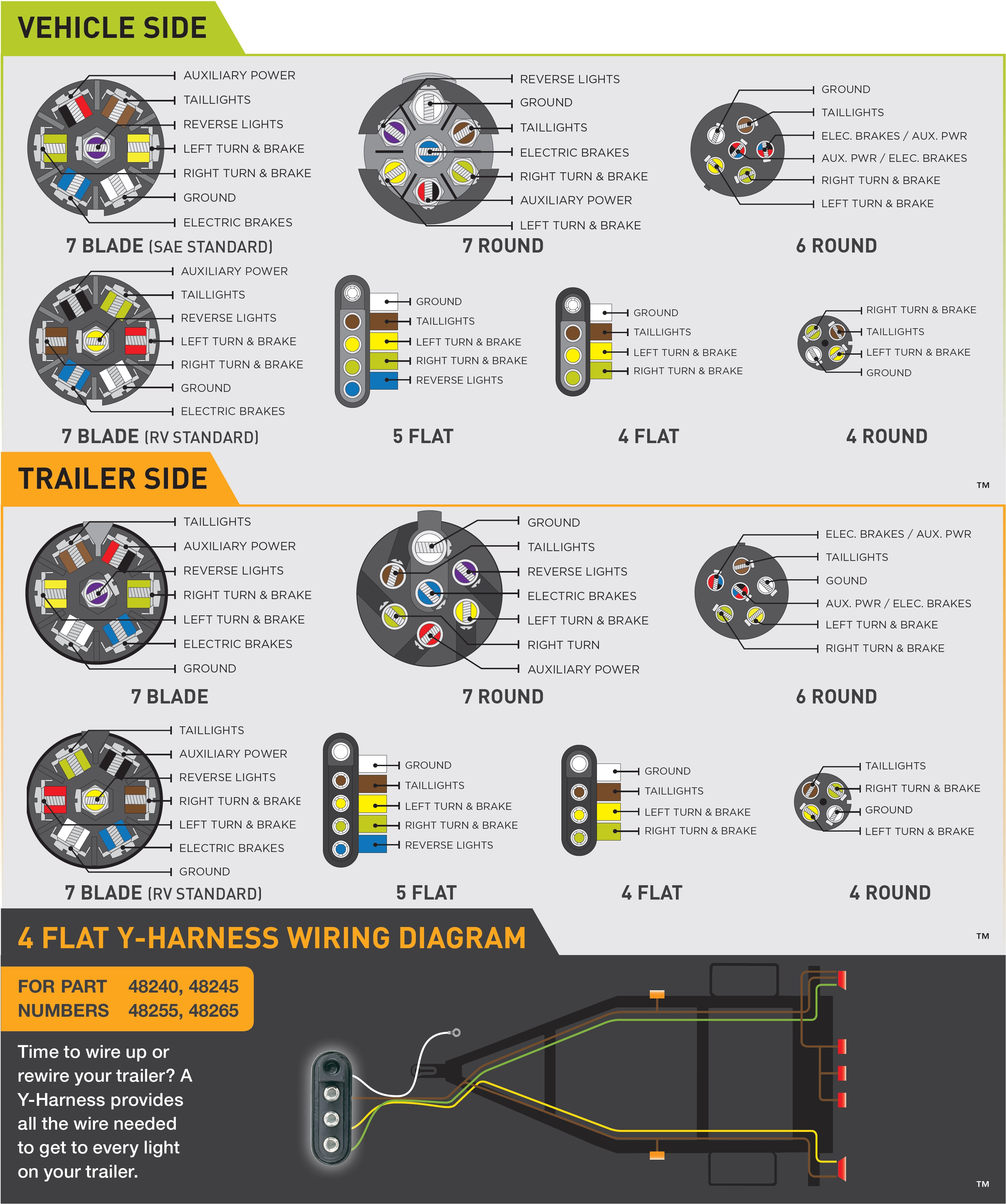
At a minimum, all trailers need at least 4 functions: Tail lights, Brake lights, Left & Right signals. 4 wires will give these functions, so the simplest scheme is a 4-pin connector. The most common 4 wire connector is the 4-Pin Flat Connector as shown here.
Electric Brake Diagram Trailer
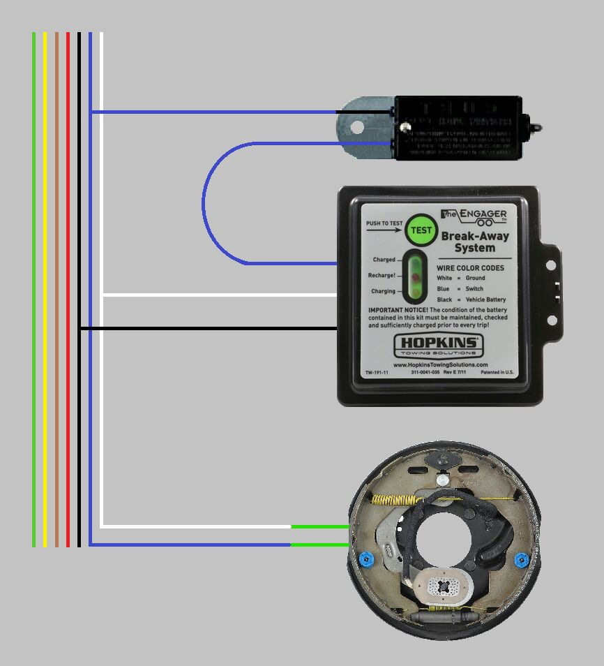
Connect the wiring harness. Plug one end of the wiring harness into the back of the brake controller. Then, route the other end of the harness towards the vehicle's 7-way trailer connector. Make sure to stay away from any hot or moving parts, and secure the wiring harness with zip ties or mounting clips as necessary.
7 Way Wiring Diagram Trailer Brakes Wiring Harness Diagram
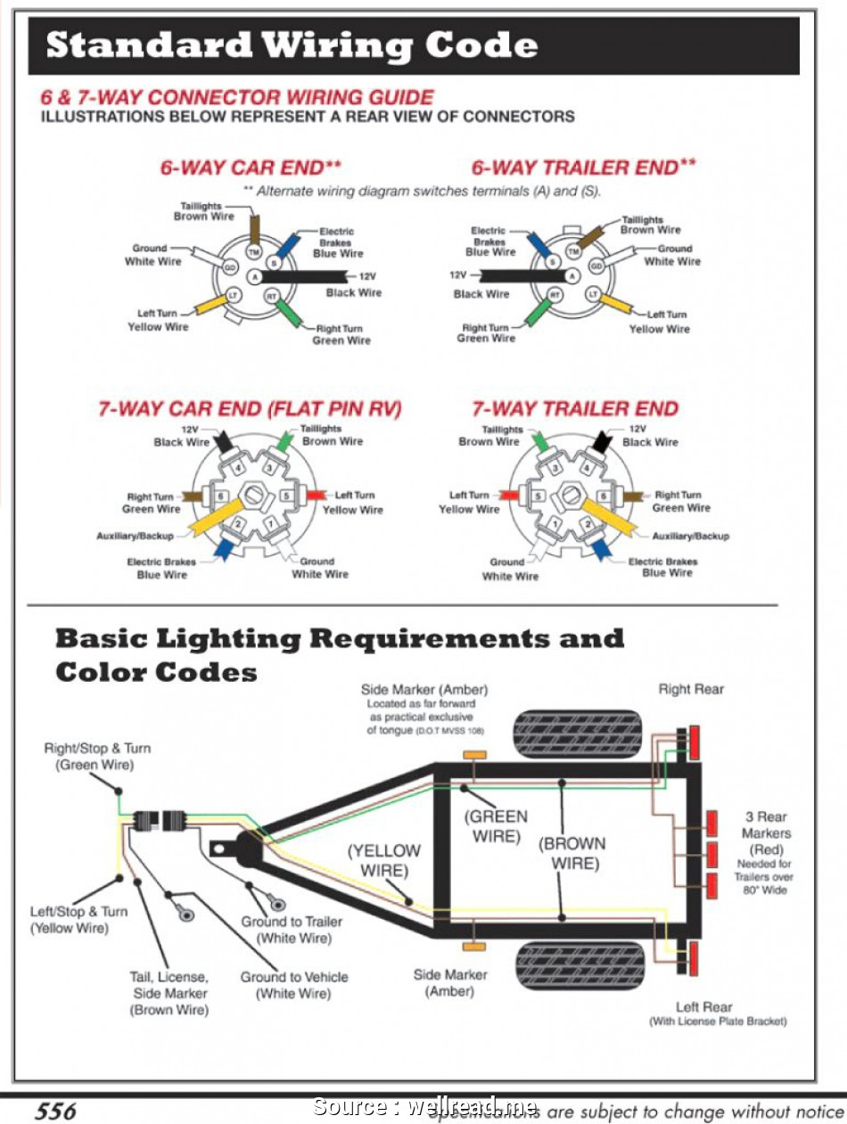
The Diagrams below show the Typical Trailer Wiring for 4 Pin Flat Connectors all the way to 7 Pin Round Connectors. It is Important to note that the "White Wire" is the ground wire, You will notice this even when you buy lights. A lot of LED Lights come with Black and White wires and people can easily confuse the black wire for the ground. A faulty and unsecured ground wire is often the.
7 Way Trailer Brake Wiring Diagram
The colors for a 4-pin trailer wiring diagram are: White: Ground wire. Brown: Tail/running lights. Yellow: Left turn/brake light. Green: Right turn/brake light. 18-gauge wire is the minimum recommended size for the 4-way plug. This should be used for the lights.
6 Pin Trailer Wiring Diagram With Brakes Headcontrolsystem
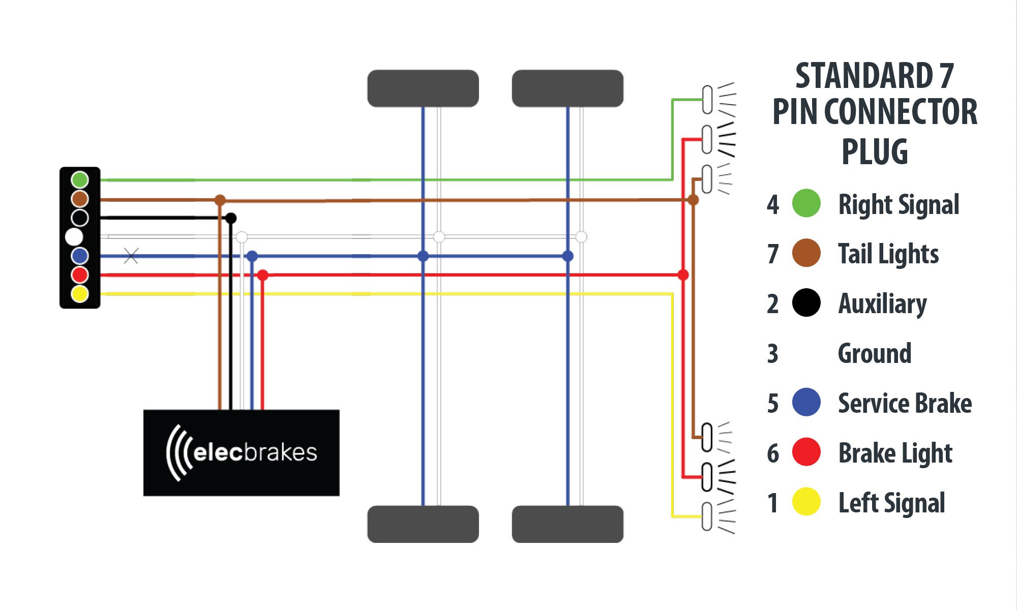
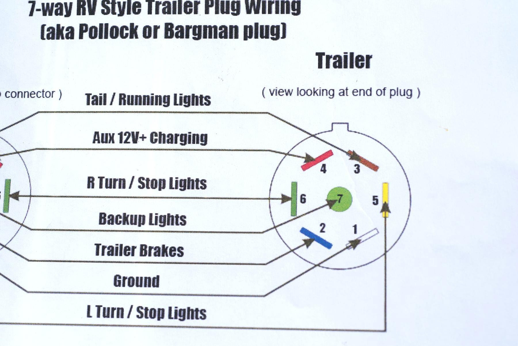
7-ways are some of the most common harnesses found on trailers. 7-ways provide the required running lights, turn signals, brake lights, and ground for the trailer. In addition, they provide three additional pins for a 12V hot lead, electric brakes, and reverse lights.