Instructions. Rinse cranberries and add to a large saucepan. Add sugar, orange juice, orange rind and water. Bring to low boil for 3-4 minutes. Lower heat to a simmer. The
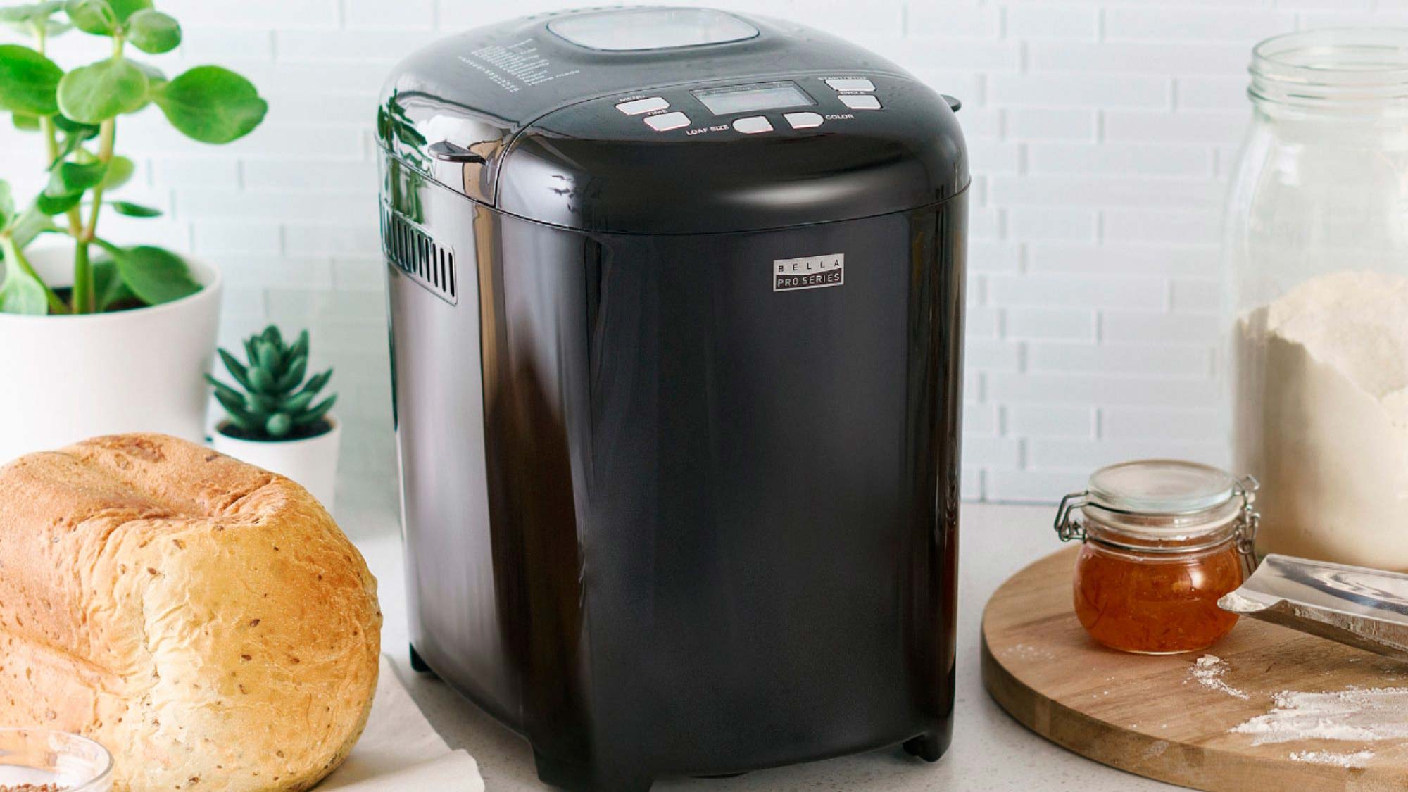
Step 3: Open your bread machine and make sure the paddle is on the spinner at the bottom of the bread maker. Pour in your mixed wet ingredients. Step 4:
3-4. High protein. 3. Quinoa. With its nutty taste, quinoa can provide you with plenty of protein and flavor in an oatmeal alternative. In addition to its impressive protein content,
Another great recipe for this frosting: Homemade chocolate cupcakes. Step 1: Prepare your pudding as instructed on the box. Step 2: Remove pudding from heat once prepared and cool completely.
Sprite is ditching its iconic green plastic bottle in favor of more sustainable clear bottles, its parent company, The Coca-Cola Co., announced Wednesday. It's a major change for the bubbly.
Brown beef and onion together, seasoning with garlic salt, then drain. While beef is cooking, cut Velveeta up into small cubes. Put Velveeta, beef, and Rotel into a crockpot and
Center your spring menu around vibrant, earthy, zesty, and tangy dishes featuring bright citrus fruits like lemon, aromatics like garlic, veggies like asparagus, herbs like basil, and tangy cheeses like
Premium beverages in convenient locations. With the premium self-serve solutions, you can offer iconic hot and iced Starbucks (R) beverages to anyone, anytime. It's the ultimate convenience for your customers.
Position 2 racks in the middle of the oven and preheat to 425 degrees F. Line 2 baking sheets with parchment. Heat the oil in a large skillet over medium-high